|
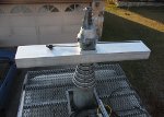
Here is visual representations of HSMM-MESH™ Networks. The top picture is ONLY AN EXAMPLE. The bottom picture is a LIVE (updates every 2 minutes) logical map of the Developers' tunnelled mesh based in Austin, TX. As long as one node can see another, devices on the network can talk to other devices on the network. Each node can relay traffic between nodes. You can see that between any 2 computers or devices, you can have multiple paths, giving redundancy in case one node goes down. Paths of different quality are automatically considered. If one path is worse than another, it gets less traffic.
If a node that is in use goes down, the surrounding nodes will automatically figure out an alternate route to pass traffic. Using OLSR, the best route is automatically determined and used.
Items connected to nodes (marked below as examples A/B/C/D/E/F) can be any network-enabled device, such as Computers, IP webcams, IP telephones, web, email, or file servers, RMS winlink nodes, network-attached-storage (lots of harddrive space), Wii/Xbox360 (should I have mentioned that?). Anything that can communicate over a standard TCP/IP network will work over HSMM-MESH™.
You can find information about other mesh networks in use on the Web Links page.
The other chart is the output of the olsr-topology-view program for Linux, available on the software download page.

This is a LIVE topology view of the Austin, TX mesh, including the Developers' tunnels. (click to enlarge in new window).
This image will update every 2 minutes, needing a manual refresh of this page.

|